skip to Main Content

RMS Situational Awareness Display (RSAD)

The Robotics Situational Awareness Display (RSAD) is a Windows based application developed specifically for NASA. RSAD provides visual steering cues and other robotics information during robotic arm operations both during training and during real-time, inflight operations. Versions of RSAD are in use on both the Space Shuttle and International Space Station programs, running on both the IBM Thinkpad 760E and A31p platforms that support the two programs. RSAD integrates data from multiple sources (telemetry, the manipulator controller interface unit (MCIU), space vision system (SVS), then merges and processes it for display to give astronauts different tools that will help him/her to have a good idea of what’s going on with the arm. This training device has decreased the number of training hours needed and saved NASA considerable money for each flight. RSAD provides multiple displays, both general purpose and task specific.

Benefits:

  • Inflight Performance & Safety
    Both crew performance and safety are enhanced during robotic operations because of the intuitive graphical view of data beyond that provided by the flight software displays and because crew members see an integrated, big picture of the activity, not just the individual task.
  • User Satisfaction
    Since development is end-user driven and iterative, users define and identify features that they need and want.
  • More Efficient Training
    During training, RSAD allows for a wide view of the situation to allow the crew to more easily determine activities of significance as they refine their approach to accomplishing mission objectives.
  • Reconfigurability
    Both mission data and user preferences are data reconfigurable allowing for fast and efficient updates and customization.
  • Captured Data
    All input data is recorded and may be used to drive the RSAD displays in playback mode or for post-processing.
  • Ease of Operation
    RSAD operations are highly automated for hands off operation during flight.
  • Robustness
    Full error detection on external interfaces and file I/O to immediately detect, isolate, and identify problems.
  • Graceful Degradation
    RSAD makes the best use of available data to drive the displays in the event of external interface errors. RSAD also reduces the display update rate as the processor becomes saturated.

Why is it Innovative or Significant?

RSAD provides an intuitive graphical view of data beyond that provided by the flight software displays. Development is user driven with the astronaut office (CB) providing the requirements and user interface guidelines. A spiral development process allows iterative refinement of the requirements and user interface, based on crew experience in flight and during training.

RSAD provides the users with a unique integrated view by merging data from multiple data sources at 2 Hz. Although specifically targeting the flight laptop environments, RSAD will run under Windows 95 or later with at least a Pentium III processor. A robust architecture supports the addition of both displays and external interfaces. The architecture provides a general solution to the task of providing multiple displays driven by multiple data sources.
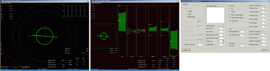
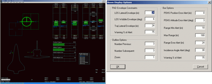
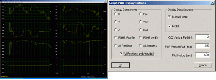
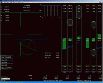
Sample Displays

The Approach Corridor Display (ACD) is a task specific display for constrained approach operations under either hand controller or joint command. The ACD consists of six components: Mating Corridor Display (MCD), Hand Controller Command Display (HCC), Corridor Equation Display (CED), Single Joint Display (SJD), Digital Data and Spinner. The width for the MCD (on the left) and SJD (on the right) portions can be adjusted and saved in a user profile. Menu commands are provided to show/hide the MCD, SJD, HCC and Digital Data portions of the display.
The BOOM is a task oriented display intended for use during the OBSS inspection of the nose cap and wing leading edges.  This display is only active when waypoints have been selected.   It consists of nine components: Hand Controller Display (HCD), Joint Information Display (JID), 2D Outline, Bar Graphs, Waypoints Table, Position and Attitude Display (PAD), POR Digitals, Digital Data and Spinner. The HCD, JID, 2D Outline, Bar Graphs, Waypoints Table and PAD components are adjustable in size and along with the POR Digitals and Digital Data components may be shown or hidden by user command.
The BOOM is a task oriented display intended for use during the OBSS inspection of the nose cap and wing leading edges. This display is only active when waypoints have been selected. It consists of nine components: Hand Controller Display (HCD), Joint Information Display (JID), 2D Outline, Bar Graphs, Waypoints Table, Position and Attitude Display (PAD), POR Digitals, Digital Data and Spinner. The HCD, JID, 2D Outline, Bar Graphs, Waypoints Table and PAD components are adjustable in size and along with the POR Digitals and Digital Data components may be shown or hidden by user command.
The Graph POR Display (GPD) provides a graphical display of the time history of the POR position and attitude components from the various enabled data sources and the POHS position and attitude errors from the primary data source.  It consists of three components:  from one to eight Graphs, Digital Data and a Spinner.
The Graph POR Display (GPD) provides a graphical display of the time history of the POR position and attitude components from the various enabled data sources and the POHS position and attitude errors from the primary data source. It consists of three components: from one to eight Graphs, Digital Data and a Spinner.
The Combo (COMBO) Display is used for generic operations. It groups three different components. The first component, the Joint Information Display, gives real time the status of each joint and indicates whether or not the arm is or will be soon in a singularity position. The second component, the Hand Controller Display, help the astronaut to move the arm to a defined target, using a green square as the representation of translations and a circle as a representation of rotations. The goal is to bring both circle and square in good shape in the center of the display. The third component, the POR Display, indicates the current and targeted position of the arm from all sources available. Onboard the shuttle, a maximum of 3 digitals can be displayed at the same time on the control panel and RSAD makes available all the digitals at the same location.
Back To Top